Project 01
Design Practice,
Engineered.
A first-year University of Bristol design portfolio showing the transition from hand-drawn engineering construction to CAD modelling and software-generated technical drawings.
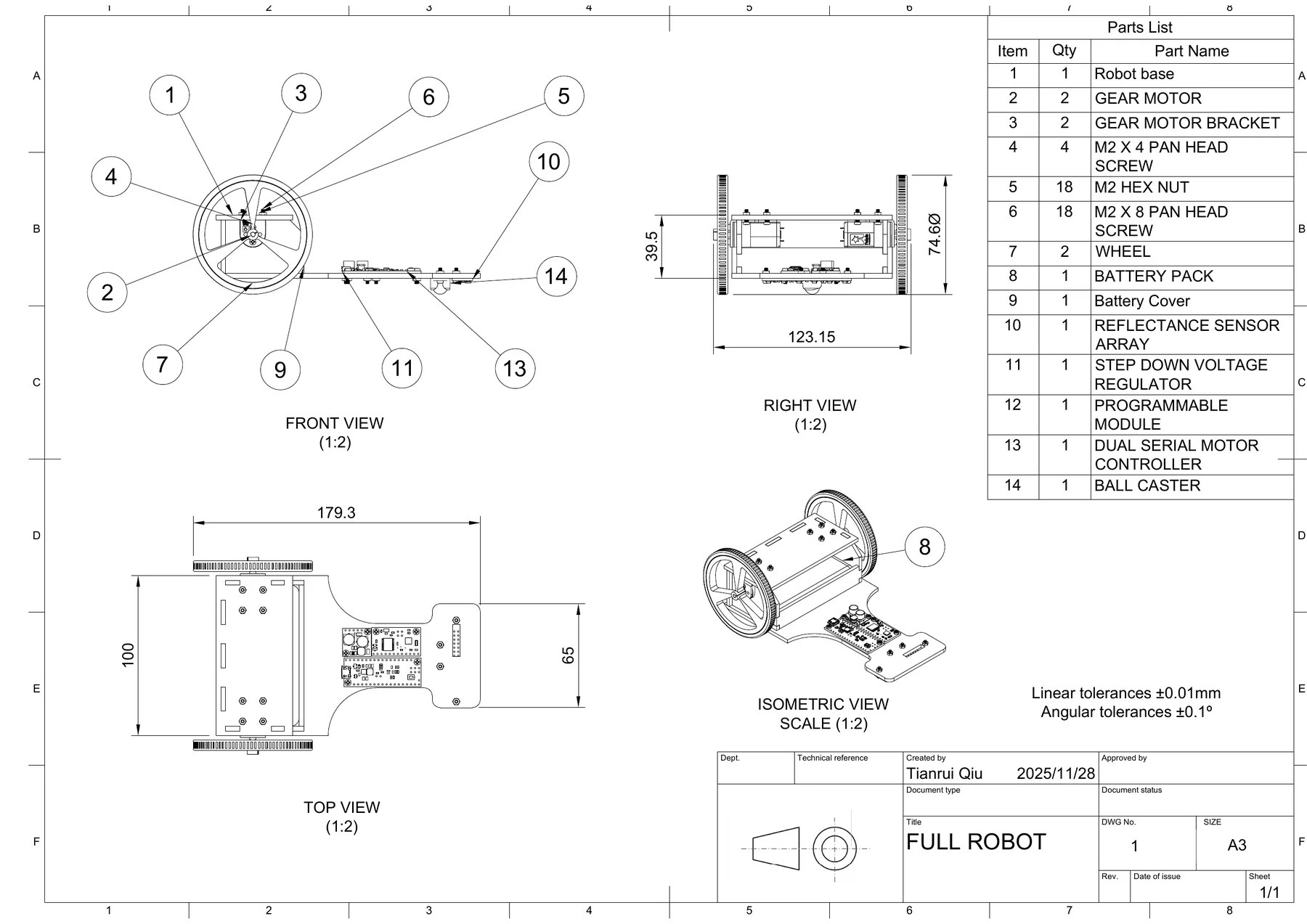
Software drawing output: full robot assembly, parts list, dimensions, and orthographic/isometric views.
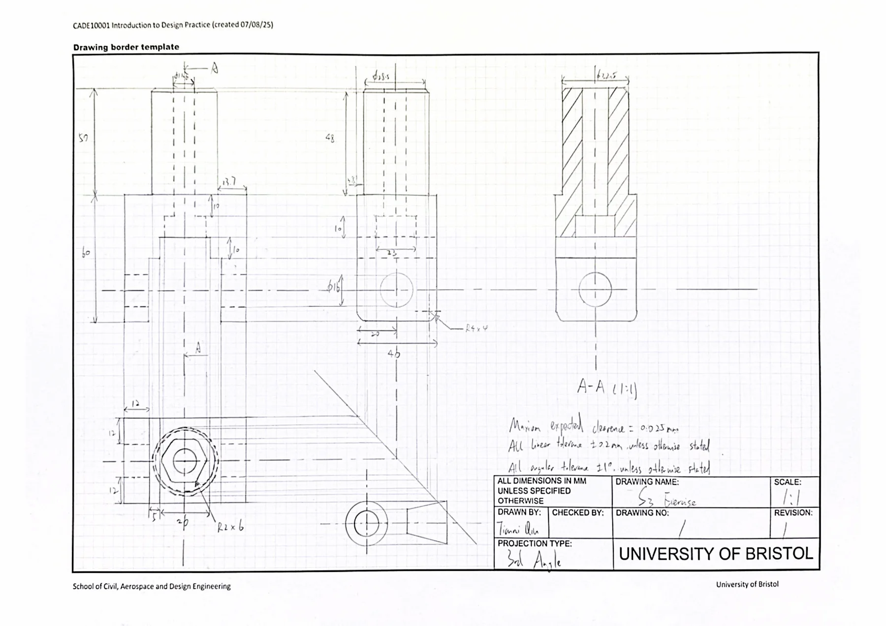
Hand construction drawing: orthographic views, dimensions, tolerances, section view, and drawing border.
Hand-built orthographic logic.
Page 4 records the manual engineering drawing stage: center lines, hidden details, section view A-A, dimensioning, tolerances, and a complete drawing border.
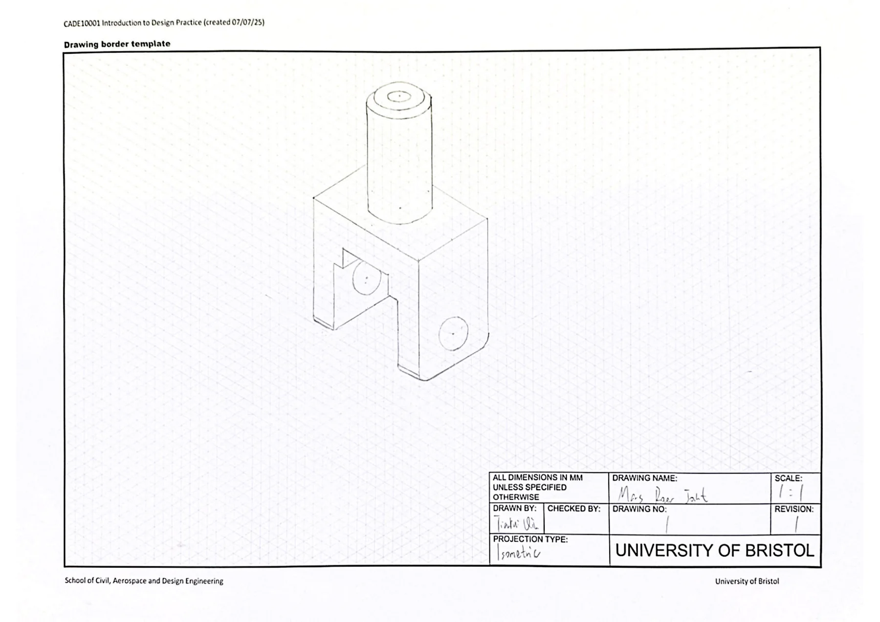
From views to volume.
Page 5 converts the part into an isometric representation, helping connect 2D projection rules with the physical 3D object.
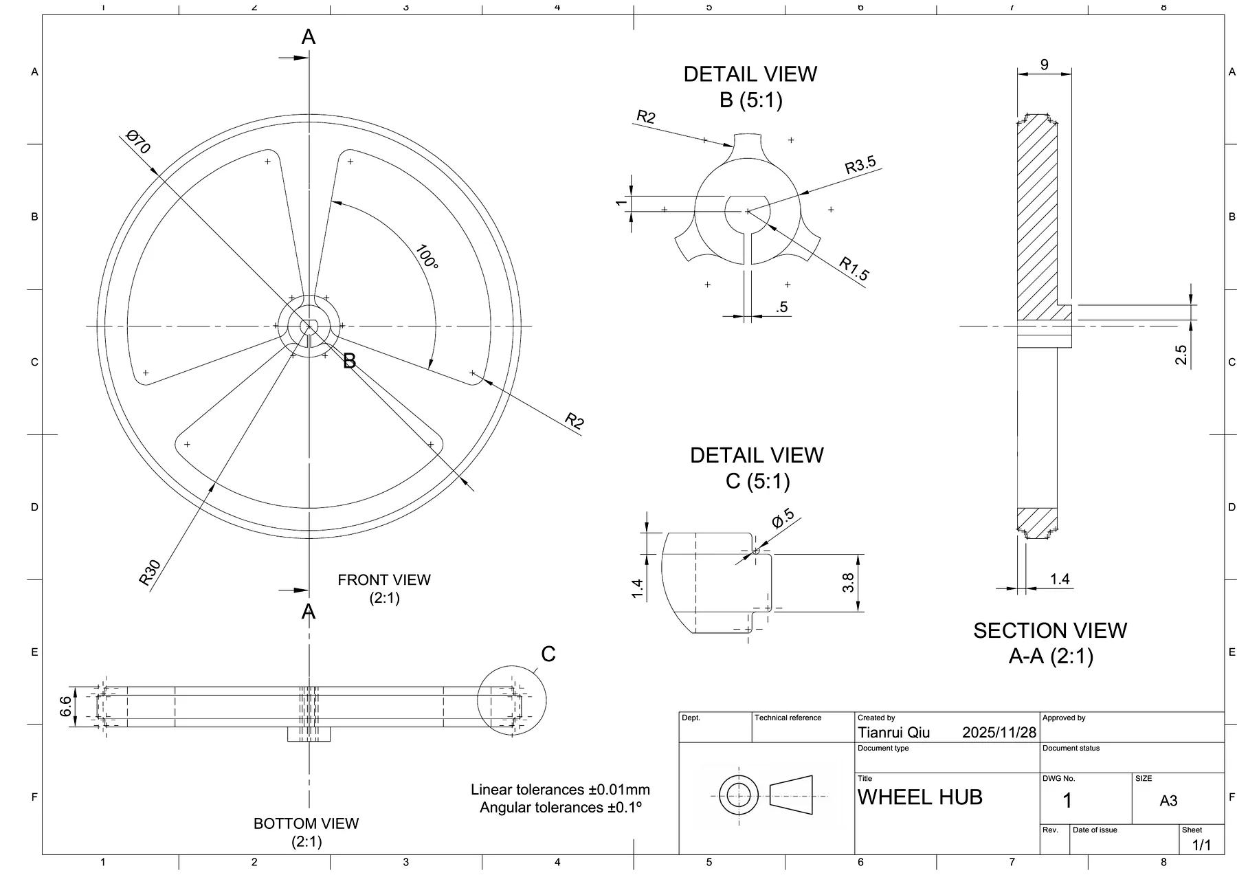
CAD geometry becomes documentation.
Page 7 shows a software-generated wheel hub drawing with front, bottom, section, and detail views, moving from sketch practice to controlled CAD output.
System-level assembly communication.
Page 8 presents the full robot drawing with front, right, top, and isometric views plus a parts list, showing how CAD output supports assembly communication.
Selected sheets
Interactive model
Full Robot Assembly
Drag to rotate. Scroll or pinch to zoom.
The Fusion 360 project file is still included as a downloadable source package. I also converted the exported OBJ + MTL assembly into a web-ready GLB, so the robot can be inspected directly in the browser.
Source Package
2773678_robot.f3z
Fusion 360 archive, original PDF, and web GLB model are kept with the project page.Core outcomes
What this project shows
Engineering Drawing Foundation
This project trained the core visual language of mechanical design: turning parts and assemblies into drawings that can be read, checked, and manufactured.
- Orthographic views, section views, hidden detail, centre lines, and drawing borders.
- Dimensioning, tolerances, scale control, and clean layout hierarchy.
- Manual sketching practice before moving into digital drawing output.
CAD Modelling & Fabrication Thinking
My main contribution was building and organising the digital model workflow, then connecting the CAD output with physical assembly and 3D-printing constraints.
- Created and refined Fusion 360 models for robot parts and assembly presentation.
- Prepared software-generated drawing sheets for key components and the full robot.
- Considered how parts would be made, fitted, and inspected after modelling.
Portfolio Documentation & Next Iteration
The portfolio turns the design process into a reviewable story, showing not only the final robot model but also the drawing decisions behind it.
- Selected the strongest drawing pages and arranged them as a clear design sequence.
- Converted the assembly into a browser-viewable 3D model for interactive inspection.
- Next step: add exploded views, part callouts, and guided camera movement.